Wireless booting and flash RAM fun
After my uncharacteristically non-verbose entry yesterday (Display!), I’m going to post a little more content
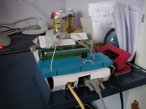
today. Yesterday I got the LCD display working with my little Python program
prototyped on the PC earlier in the week, which got me rather overexcited. The
first thing I noticed was that the sound was stuttering playing OGG files …
maybe the Python idea was a bit pie-in-the sky. Luckily changing an internal
polling interval to be a quarter of a second instead of a tenth fixed that;
though I’m now rather doubting that Python is the best idea.
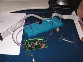
One of the other arguments against Python is the fact it’s not easy for it to
talk directly to hardware. In order to program the LCD display I need to poke
directly into physical RAM. Currently I’m doing this in a server process that
I’ve knocked up in C by modifying Embedded ARM’s sample code. The server
listens on port 4000 and with fairly minimal logic sends any incoming data on
that port to the LCD device. This has worked well enough to get the Python
process running; and has the nice side effect of meaning I can write a simple
LCD emulator Windows program (again, in Python) and develop on the PC first.
The music player library I’m using — MPD — supports generic control over
TCP/IP; so I can pretty much prototype the whole thing on Windows with the sound
coming out of the Weebox using this method.
Although this is working OK for now, in the future I’ll want to be able to put
various other status messages on the LCD display (e.g. during boot) . A quick
skirt around the internet finds lcdmod, a kernel module to control a
HD44780-compatible device connected to a PC’s parallel port. This creates a
/dev/lcd device which is then easily accessible from shell scripts etc via
simple ‘echo “Message” > /dev/lcd’ commands. Of course, my LCD display isn’t
attached to the parallel port, nor indeed does the Weebox have a parallel
port! One idea I’m toying with is modifying the code to work using the memory-
mapped hardware registers, it shouldn’t be too difficult to get working, and
could be a good way to reintroduce myself to kernel-space, being my first kernel
modifications since about 1996!