Game Development: SWAT
It’s been a long while since I’ve wrote anything worthwhile on this blog. After chatting with some workmates about life in the games industry it occurred to me that one of the more interesting things I could post about is some of the things I got up to back in the day.
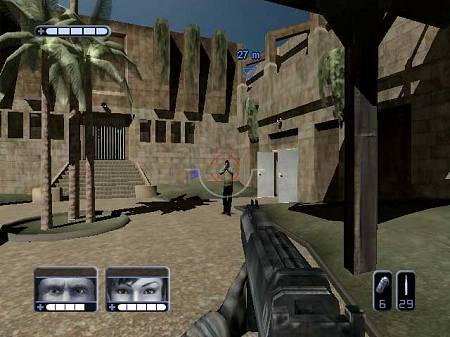
One of my favourite games to work on was SWAT: Global Strike Team. It was released on both Xbox and Playstation 2, and got an average 69 (PS2/Xbox) on MetaCritic — not the best score, but not embarrassing. Over the next few posts I’m going to go over how we came up with the idea and how that changed as the project went on, what tools we built and used to make it, and as much as I can remember from the programming point of view. I was one of the graphics coders, so my memory is somewhat skewed in the graphics direction, but I’ll try and cover everything.