Rendering in SWAT: Xbox
In this post I’ll talk a bit about how SWAT: Global Strike Team’s rendering system worked. For more of an overview and the other posts in this series, see the introduction. SWAT’s renderer was born and bred on the Xbox, so first I’m going to explain how our Xbox renderer worked. I’ll save how we crowbarred this onto a PlayStation 2 for the next post.
Xbox rendering pipeline
Okre used a pretty standard lighting model (called Phong shading), where light is considered to come from three sources:
- Ambient light: a constant amount of light received by all surfaces. It approximates the general background amount of light that’s bounced everywhere. A little like the light you get on a cloudy day; it has no obvious direction but just lights everything evenly.
- Diffuse light: a contribution from each light that depends on the distance from the light and the angle between a surface and the light. The more directly the light hits the surface, the brighter it is. A surface for whom the light only just grazes is hardly lit at all.
- Specular light: the “shiny” part of the lighting, sometimes called specular highlights. It depends on the distance from each light, and the angle between the camera, the light and the surface. It represents the light that bounces directly off the surface straight into the camera.
Okre’s overall lighting and texture for a single point on in space was, roughly:
// What colour (RGB triple) should we render a point,
// given its position, normal and shader.
Colour ColourAtPoint(Position p, Normal n, Shader s) {
  // Start out with a constant ambient colour, plus
  // the shader's contribution (its "self illumination")
  Colour diffuse = kAmbientColour + s.SelfIllumination();
  // Okre had a limitation of a monochrome specular
  // component in order to fit the diffuse and specular
  // into a single 32-bit colour value.
  float specular = 0.f;
  for (Light l : lights) {
    diffuse += l.Diffuse(p, n);
    specular += l.Specular(p, n, s.Shininess());
  }
  // The call to Shade() here runs the shader, sampling
  // textures etc, blending them and returning a colour.
  Colour colour = diffuse * s.Shade();
  // Add on the specular contribution.
  colour += specular * s.SpecularColour();
  return colour;
}
This routine was effectively run for every visible pixel in the game. The Xbox had fairly flexible graphics hardware capable of doing all these calculations, but its pixel shader unit only had space for a very limited number of instructions (between 8 and 16). There’s no way that we could have fitted ColourAtPoint into a single shader1, so we had to split the process into several stages, some requiring the world and object geometry to be drawn multiple times, and others being single full-screen passes.
The rendering process for a single frame went something like:
- Clear the screen.
- An ambient and “Z stamp” pass.
- Several lighting passes, one per light.
- A single texturing pass.
- A specular application full-screen pass.
- A gamma remapping full-screen pass.
- A colour bleed full-screen pass.
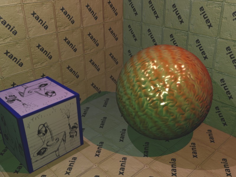
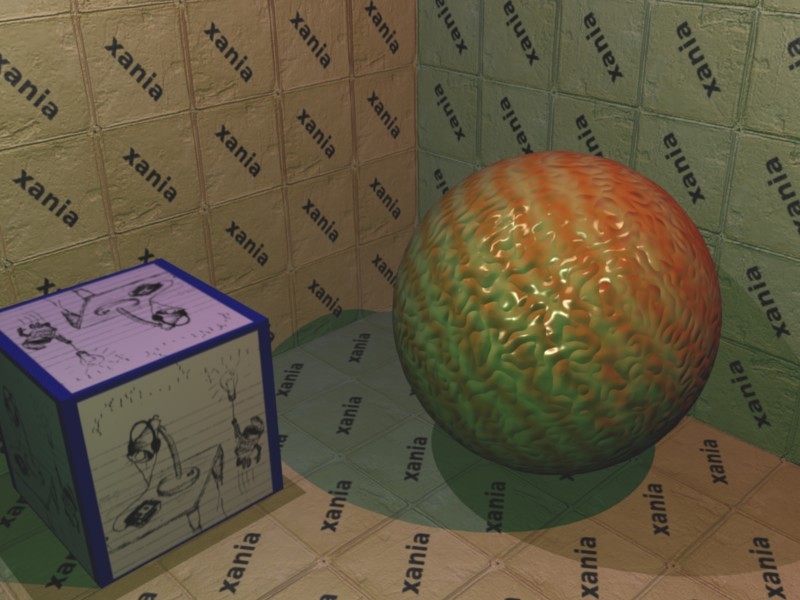
I’m going to use a rather unusual image to demonstrate how the final picture was built up. My artistic skills are limited, but I built it using the same steps as Okre would have used. There are three lights, a flat cube with a picture on it, a shiny bumpy sphere and a tiled background, the tiles having a “xania” motif on them:
Ambient and “Z stamp” pass
First the screen was cleared to a constant colour (the kAmbientColour of the above routine, with an alpha of zero.) The Z buffer2 was also cleared at this point.
Next, we used a few Xbox-specific features: the ability to count the number of pixels actually rendered, a fast rendering mode when texturing was disabled, and its fast hierarchical Z buffer3 which allowed it to quickly reject pixels that are behind previously drawn surfaces. We sorted the geometry so that the first things drawn were nearest the camera. For each chunk of geometry we also count the number of pixels actually drawn. For surfaces with default ambient settings, we only wrote to the Z buffer. For surfaces with a different ambient setting (e.g. a self illumination texture), we also added their ambient value onto the screen.
At the end of this pass:
- The Z buffer has been set to its final value. Any further rendering can turn off Z writing, which speeds up rendering a little. The front to back sort, plus the fast reject mode, means that geometry hidden behind other geometry is virtually free to render.4
- The screen buffer contains the ambient contribution of every pixel (
kAmbientColour + s.SelfIllumination()). - For each chunk of geometry, we know how many pixels were actually rendered. As we’ve sorted front to back, anything that was completely obscured will have a zero pixel count. If this is the case, we now know that we don’t have to render this chunk of scenery again this frame. This gives us screen-space visibility set culling. However, as the graphics processor runs asynchronously with the CPU, we need to block here while we wait for the pixel count results to come back. This is the point where we ran the AI code on the CPU while we awaited these results.
Lighting passes
If you could see the screen buffer now it would look pretty bland. In most cases it would be a constant, very dark grey. There might be a few bright streaks near the top of the screen where strip lights have been drawn — they would have had a self illumination map where the strips were painted in bright white.
The lights that affected the currently visible scene were found — any lights whose sphere (for omnidirectional lights) or cone (for spotlights) of influence overlapped the visible frustrum.
Then a lighting process was repeated for each of the lights.
Shadows
First, the stencil6 buffer was cleared. Then a special rendering mode was used on all the dynamic objects that cast shadows: using some vertex shader tricks the original geometry of the shape was distorted and extruded away from the light into being the shadow volume of that object. The pixel renderer was set only to update the stencil buffer, and to increment it for all front-facing polygons, and decrement it for all back facing polygons5. This has the net effect of cancelling out for all pixels except those in shadow, which would be left with a non-zero stencil value.
Next, the offline precalculated per-light geometry (remember this from an earlier post), was used to add the light’s influence to the screen only where the stencil buffer is zero. This beautifully combines the offline calculated static scene geometry’s shadows (where shadow areas aren’t even present in the geometry), with the dynamically generated shadows (where per screen pixel we know if that pixel is in shadow or not).
This covers the shadows from dynamic objects being cast onto other objects. However, we also handled shadows being cast from the scenery onto the dynamic objects. Given that the scenery information is heavily preprocessed we couldn’t use the same system for the moving objects. In this instance we used shadow buffers. For each light and dynamic object pair, we stored a texture holding a render from the light’s point of view, looking at the dynamic object. This texture only stores the Z buffer of the render: that is, for each pixel of the texture it stores how far away the nearest surface is from the light in the direction of the object.
Then when it came to rendering the dynamic objects we’d also work out for each pixel of the object which pixel of the shadow buffer corresponded to a ray going from the object to the light. We could calculate the distance from the point on the object to the light; and if the value in the shadow buffer was less than this value we knew there must be a piece of geometry between the light and the object and thus it was in shadow.
Calculating the shadow buffers was an expensive operation, so we had a series of different resolution caches, and deliberately rendered an area wider than was strictly necessary for each object. That meant the same shadow buffer could be used for as long as the object didn’t physically move too far, which was generally the case.
For further reading, see “shadow volumes” and “shadow buffer” on Wikipedia.
Texture lookups
The light’s influence was calculated per pixel using a complex set of vertex shader, pixel shader and texture operations. The Xbox supported reading from up to four textures at once, and it also had support for 3D textures and cubic environment maps.
3D textures are exactly what they sound like: an x by y by z array of colours. Obviously, being cubic in size makes them quite large. In SWAT we used a 32x32x32x8bpp texture, and in it we stored a map sampling the fall-off function of the light. This function is generally fairly complex, involving a quadratic falloff7, so it’s too expensive to calculate per pixel. Instead we mapped the position of each pixel in 3D into a position relative to this map, so that 0, 0, 0 corresponds to the a point directly on top of the light, and 1, 0, 0 maps to a point at the very extent of the light (in the X direction), and so on. Then sampling the texture at this point would give the brightness component of the light due to the distance of that point from the light. The bilinear filtering that the texturing hardware does means the relatively low-resolution texture doesn’t look blocky.
The cubic environment map is a slightly odd thing: it’s actually a set of six textures, conceptually arranged as the faces of a cube. When sampling from such a map, the texturing hardware considers the 3D U, V, W coordinate given to it to encode a ray vector. A ray is shot out from the centre of the cube in the direction of the vector, and the texture colour of the part of the cube where it intersects is sampled.
The original intention of these maps was to give a nice way of doing reflective objects (environment mapping), where you would draw the scene as seen from the point of view of the reflective object into the six textures. Then when rendering the object itself, you’d use the reflection of the object’s surface normal to sample the map, giving a shiny-looking result.
However, we didn’t use the map in this way for lighting. Instead, we created a special cubic map where for each of the pixels of the six texture maps we store a colour representing the normalized vector in the direction of that pixel. Then during lighting we can passed in the normals of the vertices into this map, and this texture lookup re-normalizes the vector. This allowed us to linearly interpolate the vertex normals (which is technically incorrect), but then re-normalize them per-pixel (to get back the “right” value). We also used the map to normalize the vector from the camera to each point on a surface, used in calculating the light reflecting back towards the camera (the specular highlights).
Each surface could have a bump map: a texture which encodes the surface normal8. This allows otherwise flat surfaces to appear to have a bumpy appearance. For example, a large tiled wall could be drawn as a single flat polygon with both a texture map of the tiles, and a bump map of the tile normals. The grouting between the tiles means the edges of the tile “stick out” a little, and so the top edge of the tile tends to catch more light than the rest of the tile. In Okre, we also stored how “shiny” each pixel was in the bump map: the alpha of the colour encoded this information. In the tile example, the tiles are much shinier than the grouting between them, so we’d factor that into the map too.
The normal stored in the bump map was always stored as if “up” was in a particular direction, usually y being up. This is fine if the object you’re applying the bump map to is facing “up”, but most objects can face in all directions. Going back to our tiled wall, in a corridor with the tiled wall on both sides, you’d want to use the same bump map on both walls, but on one wall the normals need to point in one direction, and on the opposite wall they need to point in the opposite direction.
To account for this issue, we stored an “orthonormal basis” for every vertex in the scene. This is a transformation for that vertex which takes a normal stored in bump map space into the space that the model was designed in. Fortunately, determining the orthonormal basis for every vertex is something that could be done in an offline preprocess, though is does mean storing a 3x3 matrix per vertex.
Per-pixel lighting calculation
So, armed with our various maps (3D light attenuation map, cube map normalisation map, bump map), and our per-vertex information (vector to the camera, orthonormal basis, vector to the light) we can calculate the lighting.
For each pixel, we look up the bump map, transform it into model space using the orthonormal basis, and then use that as the normal for the lighting equation. The vector to the light is looked up in the normalisation map and then reflected by the normal to get the direction the light’s rays would bounce at this point.
The vector to the camera is also looked up in the normalisation map, and then the dot product between these two values is taken: this gives the cosine of the angle between the two vectors and so will return a value close to 1 when the light is bouncing straight at the camera, slowly fading to zero at a 90 degree angle away from the camera. This value is raised to a power and then used as the specular amount. The power detemines how “shiny” the object appears: high values will give a tight, focused highlight, lower values a more matte effect. The alpha component of the bump map is multiplied in too, giving some per-pixel control over the areas that are shiny or not.
The transformed bump map normal is also dot producted directly against the normalised light direction and used as the diffuse contribution of the light. The final output of the pixel operation is to add the light’s colour times the diffuse amount to the colour of the screen, and then add the specular component to the alpha part of the screen.
This rather lengthy process was repeated for each light. One advantage was that the number of state changes between surfaces was kept to a minimum: only the bump map and a few constant values (e.g. the light position) changed between rendering of lights, so despite its complexity it ran pretty fast.
If you could see the screen now, you’d see an untextured diffuse lit scene. All the lights’ influences have been added to the ambient from the ambient pass, and the shiny specular part is hidden away in the alpha component of the screen. In the test scene I introduced earlier, the screen would look like:
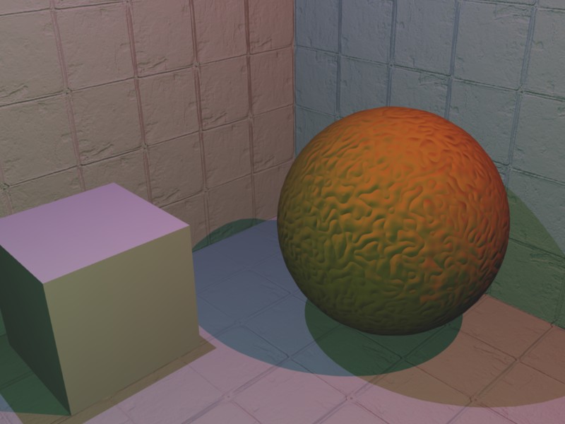
The contents of the red, green and blue channels after lighting, but before texturing.
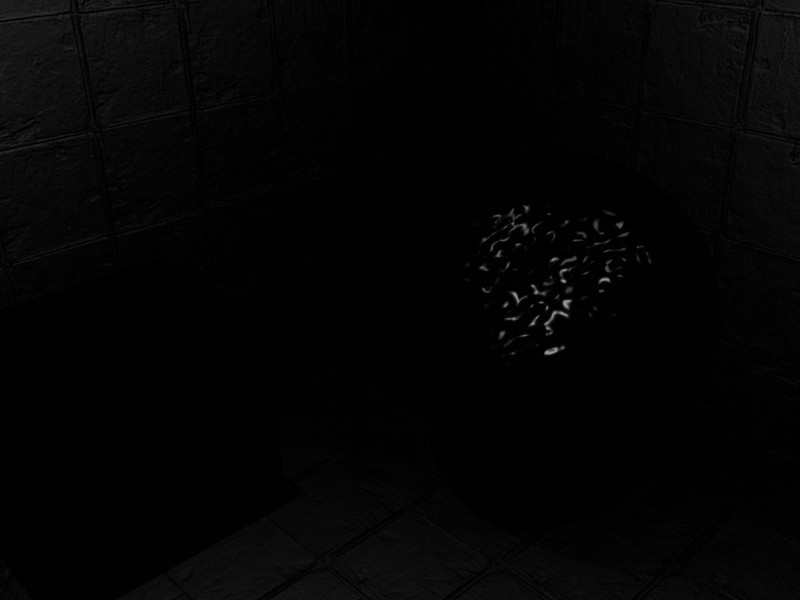
The contents of the alpha channel.
Texturing pass
Compared to the lighting pass, the texture pass was pretty simple. For every object on screen, we ran its precompiled shader to get its final colour at each pixel, and then multiplied this with the screen, ignoring the on-screen alpha9.
At the end of the textuing pass, we have a fully textured, diffuse lit scene. The alpha channel is unaffected in this pass.
The textured, lit buffer (just showing red, green and blue).
Full screen passes
The final few stages of the renderer operated on the whole screen, running a pixel shader that read the current colour at each pixel, processed it, and then wrote it back. The passes were:
Specular application
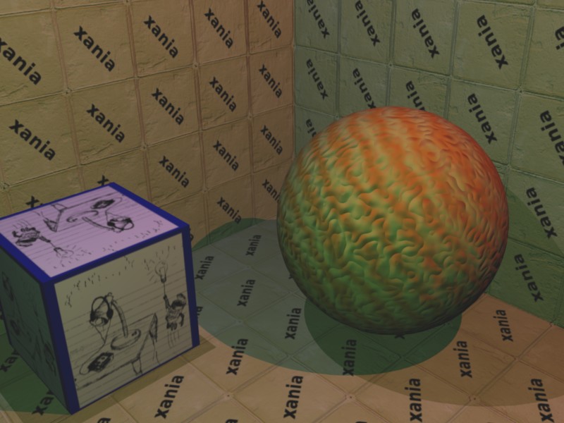
Remember that so far we’ve calculated the monochromatic specular component of the lighting and written it into the alpha of each pixel, but it’s invisible. In this pass we simply add the specular alpha value to the red, green and blue colour components. At the end of this pass you’d see a fully lit and textured scene.
The results of adding the alpha channel to the red, green and blue. A fully lit scene.
Gamma remapping
Based on the virtual camera’s aperture and exposure settings and gamma settings we calculate a mapping table for red, green and blue values. Each pixel would be looked up in these tables. At the end of this pass, the scene would have the very dark parts become black, and parts brighter than the current aperture and exposure could epxress would have been mapped to white.
Colour bleed
To simulate the very bright areas bleeding out we apply a bleed filter: first we copy the screen out to another buffer, and while doing so discard any pixels below a threshold intensity, replacing them with black. This buffer then holds just the very bright areas of the screen.
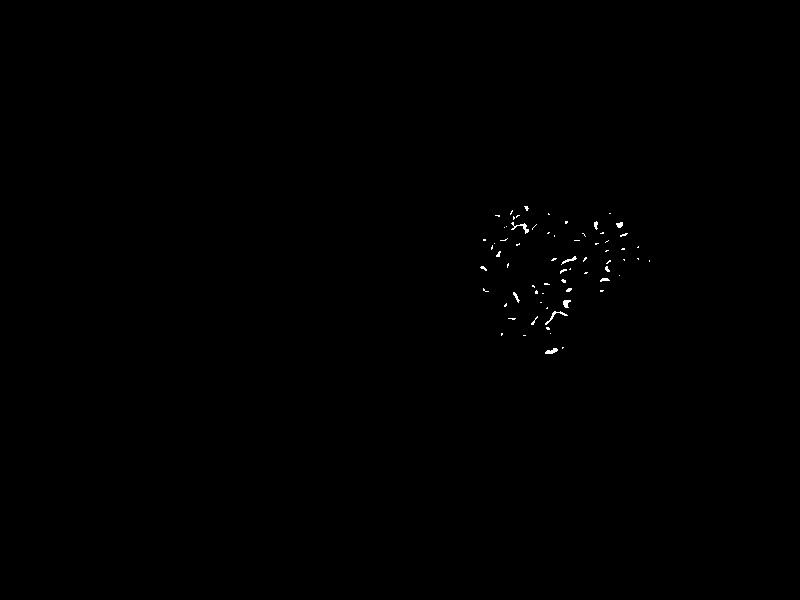
Just the brightest parts of the scene.
We progressively shrunk that buffer down into other buffers, reducing the intensity each time. This leads to a series of images, each darker, and smaller than the previous. Adding these all back together (with appropriate scaling) gives a highly bled-out representation of the high intensity parts of the original screen.

Just the brightest parts of the scene, this time blurred.
This is then added back onto the screen, giving us the final image.
Endnotes
That explains the majority of how the Xbox renderer worked. I’ve been a bit vague on some details: if you can bear more in-depth explanations please contact me and I’ll happily go into any amount of detail.
Next time I’ll go into how we managed to get this very texture heavy and pixel and vertex shader dependent system onto a Playstation 2 — which has very limited texturing and blending capabilities.
-
Though nowadays on DX10 hardware you probably could! ↩
-
The Z buffer is a screen-sized buffer that stores the distance that each pixel is away from the camera. It’s used to work out when a pixel about to be drawn is in front of or behind the current pixel on the screen. ↩
-
This holds extra information per 4x4 block of the screen, storing the minimum Z value within this block. During coarse rasterisation, the Z extent of a whole 4x4 block can be compared against this single value, and the whole block can be discarded if it’s completely behind the current block. ↩
-
In fill-rate cost anyway. ↩
-
Actually it was more complex than this, using z-fails instead of z-successes for updating the buffer to solve a problem when the camera is inside the shadow volume. ↩
-
The stencil buffer is a simple 8-bit value for every pixel on the screen, typically to store temporary results during real-time shadow calculation. ↩
-
Okre used a
(1 / (1+8d2) + ¼)(1-d)falloff for omnidirectional lights. For spot lights, we used a two-dimensional circular falloff texture, and applied a distance falloff using the vertex shader. ↩ -
The mapping was pretty simple; the red, green and blue texture colour encode the x, y, and z of the normal, with
0x00being -1,0x80being 0, and0xffbeing +1. An aside: some platforms, e.g. the Dreamcast used spherical polar coordinates for their bumpmaps. ↩ -
Transparent objects were handled completely separately and were a nightmare, so I’m not going to go into too much detail here. This is already far too in-depth! Essentially they were sorted and lit differently and put into the scene afterwards. ↩